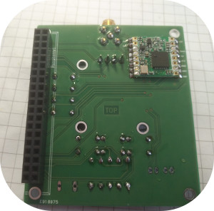
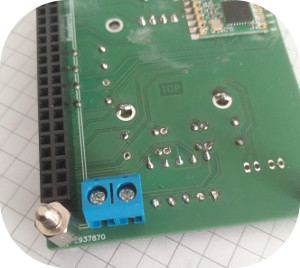
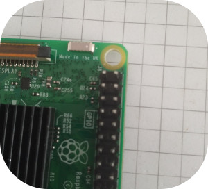
As a first consideration you should determine which spacers you have available.The Raspberry pi provides holes for M2.5 screws .Due to the fact these are difficult to obtain on the open market, you can also drill the holes to 3.5 mm diameter without damaging any connections. The same goes for the LoRa Shield.
In the holes with 3.5 mm diameter, you can use the commercially available spacers with M3.
However, caution is advised because you are likely to lose the warranty of a new Raspberry.
Here's the shield with its front and back.
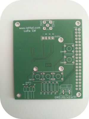
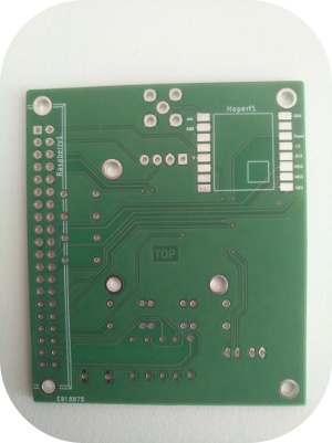
First, I recommend soldering the HopeRF. A flux pin helps with soldering. The easiest way is to apply solder to the pads for the HopeRF and then align the device (please pay attention to the alignment of the HopeRF ! It is upside down ! The reason for this is to keep the antenna connection as short as possible).
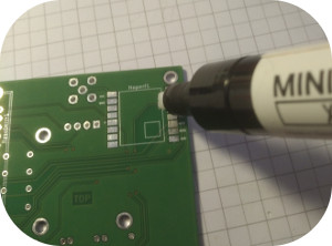
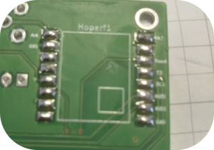
If the HopeRF is aligned, the pads can be heated with a soldering iron and fixed with a little pressure on the HopeRF. If necessary or checking the contacts with a continuity tester can still be soldered.
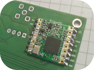
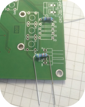
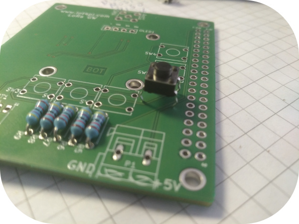
Then I recommend to mount the resistors and the buttons. With the buttons you have to take care of the alignment. If the antenna connection on the board is defined as above, the switch should be aligned so that the same connections are horizontal. If the switch is pressed there should be a contact between upper and lower pins. In the picture shows the orientation of the switch, which can be recognized by the bending of the pins. However, a control saves you from later trouble!
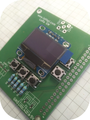
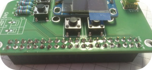
Now you can mount the OLED display and the 40 pin connector.
At the end the SMA connector and if necessary the connector for the 5V power supply can be mounted.
The 5V connector can be mounted on the bottom so that it does not touch any components on the Raspberry pi 2 or 3.
